|
 |
||||
One thing that bothered me in my sleep was some wobble that I saw in the holes for the z-brackets. I should of stopped and figured out what was causing it right then and there, but you know how it goes. It wasn't bad at all. So before I did the same stupid thing to the left tank brackets, I gave the drill press an exam. Turns out that I do have a wobble in it. Looks like the shaft is bent. DOH, this sucks. 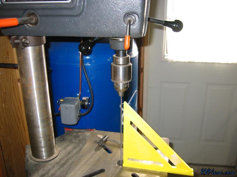 Next I match drilled the tanks and de-blued the back edge of the tank so I could countersink the tank skin to baffle holes. These get countersunk to make it easy to slide the baffle in when all of the ribs are riveted. Makes sense. UPDATE: Before I countersunk these holes, I removed the baffle from the skin, realized I missed a step, clecoed it back on, then countersunk. Now this all sounds fine and dandy, but when I riveted the baffle to the skin, I had a lot of rivets that weren't sitting perfectly flat. However my left baffle was perfect. DO NOT UNCLECO THE REAR BAFFLE UNTIL YOU COUNTERSINK THE SKIN!!! If you do, set a rivet in the holes to check for perfect alignment, or ream out the hole. 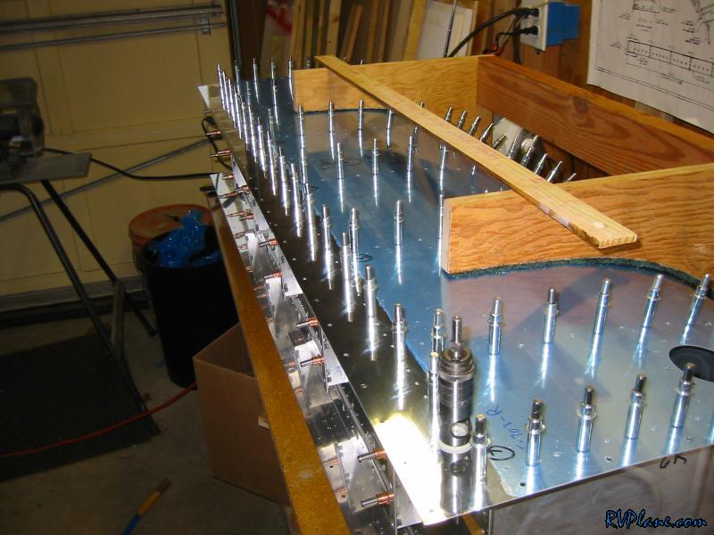 I coutersunk these holes and then enlarged the skin-spar holes to #19. I did this with a #30 bit, then a unibit (5/16") and then a #19 bit. Using no common sense, I put the unibit into the air drill and tried that for the first hole. NOT A GOOD IDEA. Lots of chatter and a crappy result. Luckily, the #19 bit cleaned it all up. I was very lucky. I Unitbitted the rest of the holes with my cordless drill with great success. 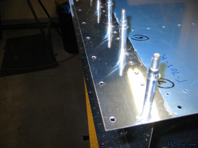 Next I wanted to tackle fabricating the tank to fuselage attachment angle. This is one thick piece! 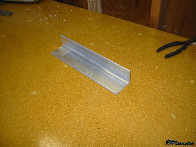 This is what Van's gives you to put on the back of the rib. The thick angle goes on the front to sandwich the rib. I used this to act as a template for fabbing up the angle. 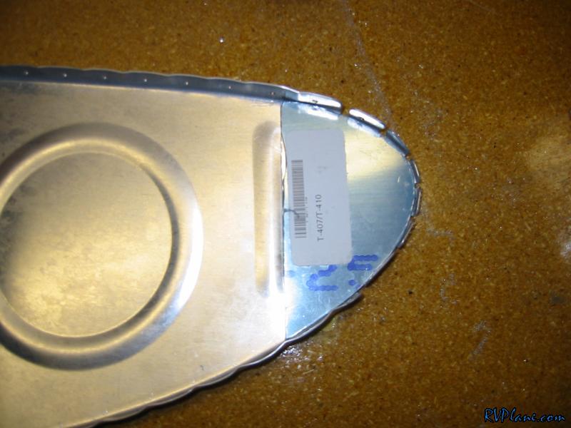 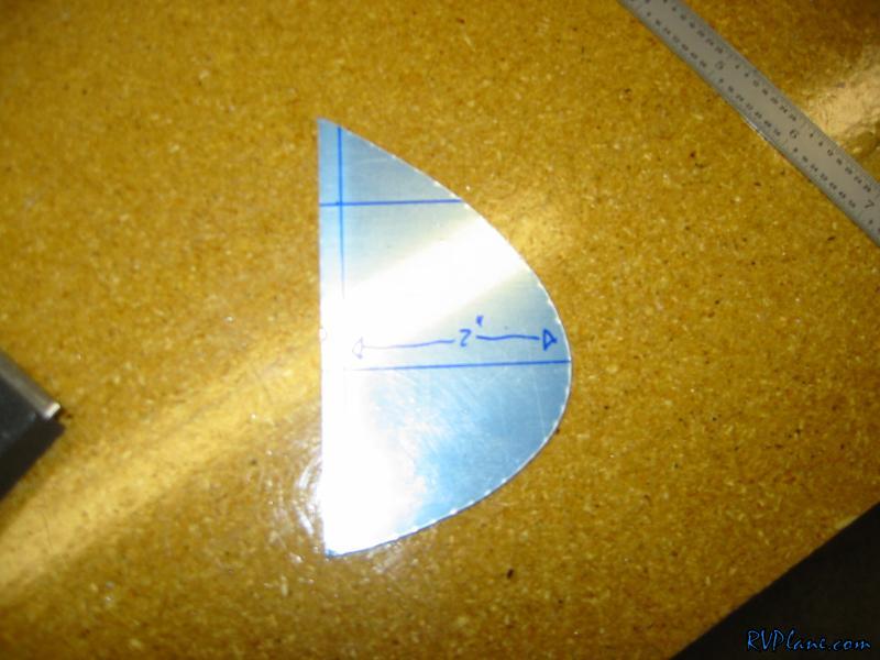 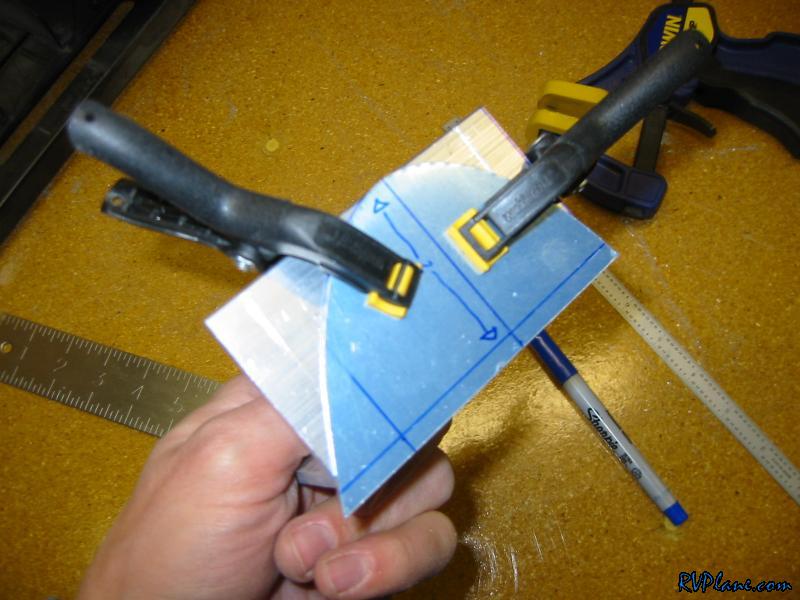 Tracing worked very well. 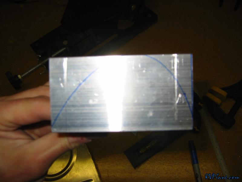 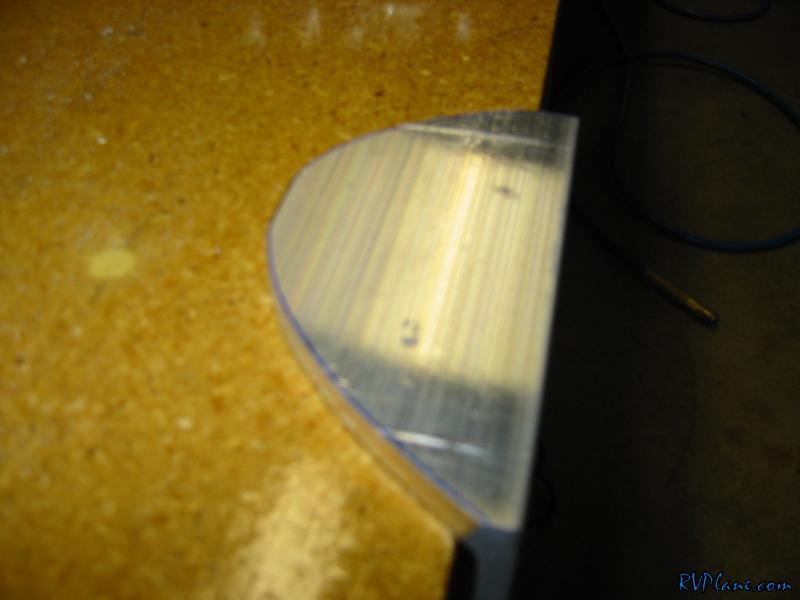 Good first fit. 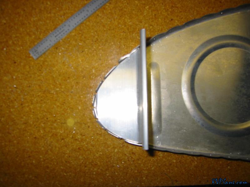 Now onto the other side. 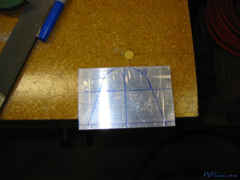 And the final product. It took A LOT OF WORK to make this. Look at all of the metal shaving/dust on the table. These are from the hacksaw, vixen file and mostly from the bench sander. 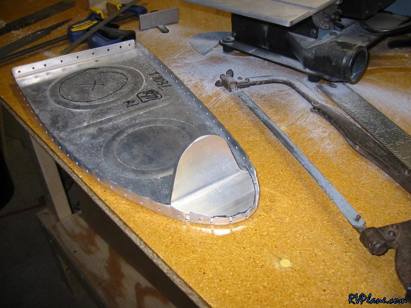 Van's has a recommendation for the rivet layout for this attach angle, but no specific callout. I used some logic and came up with this. I put some of the rivets a little more inboard just in case I have to trim it. 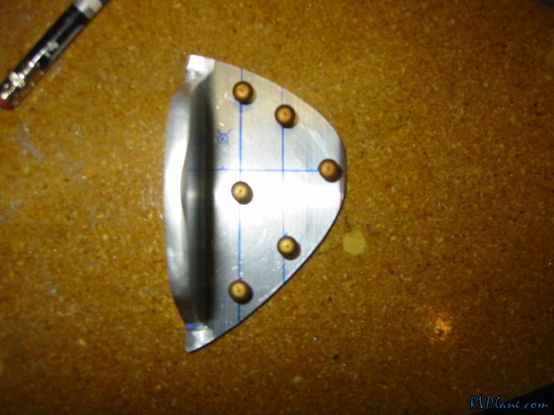 The cutout of the leading edge for the cradle came in real handy here. 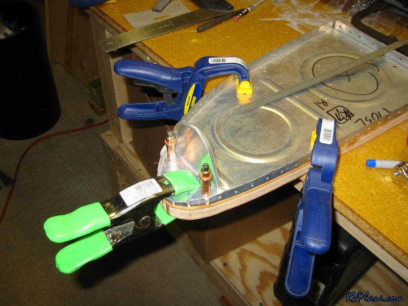 Then I lined up the backing plate and drilled it.  Wow this place is a mess. I need to get the other fuel tank at least on the other wing so I can free up some space to mess up. 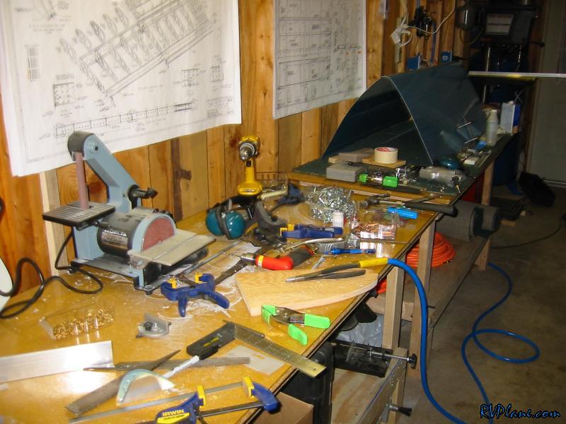 I started to work on the capacitive fuel sender lastly, but it wasn't meant to be tonight. RV 4, 6 and 8 mentioned here. The RV-8 has pretty much the same wing as the -7, and all the lines work for that. 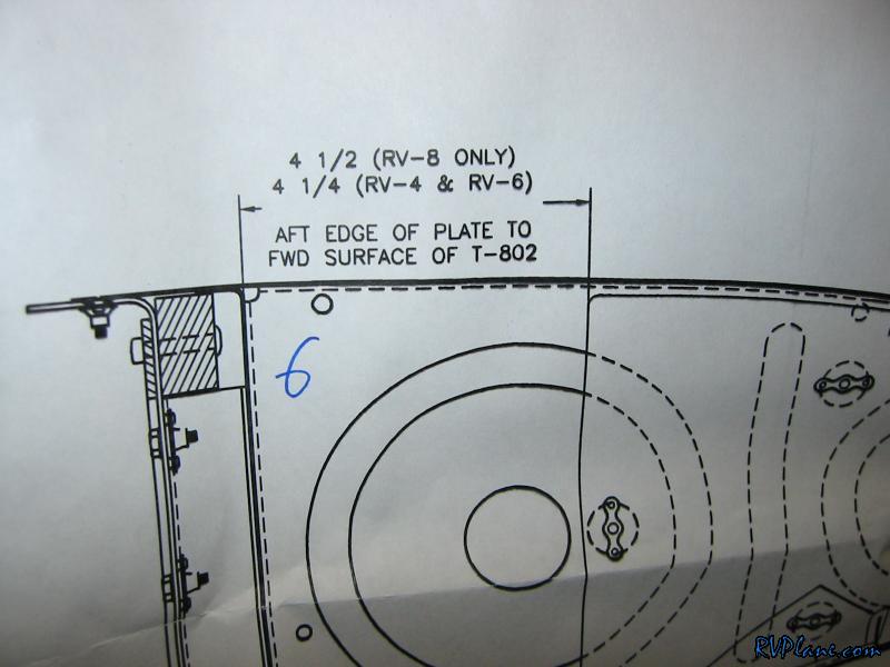
|
|||||
|
http://RVplane.com |
Last Modified: January 31, 2026 |