
|
 |
||||
The compression on my #1 cylinder for my annual were lower than the other ones - 68/80, while my other cylinders were in the mid-to-high 70's. I ran this by my A&P and he recommended running the engine for 10 hours and then performing another compression check. Well, down to SNF and back was about exactly 10 hours. I went for a quick flight to warm up the engine and then decowled the airplane. I was happy to see the compression was where it was supposed to be at 76/80. 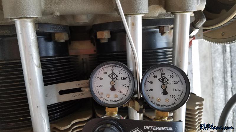 I also added some firesleeve between the baffling and the fuel flow meter in an attempt to keep my fuel as cool as possible. 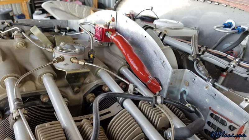 Next up was checking the valve guides on my #1 cylinder. When I started the engine at SNF, for a good 60 seconds my engine ran really rough, pointing at my #1 cylinder having issues. Seemed like the perfect signs of "morning sickness" indicating a sticky valve. I used my previously made valve tool to compress the springs and check for the looseness of the valve within the guide. Good news here again - the valves moved perfectly up and down the guides! 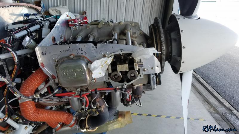 So my #1 issue with my home-made valve compression tool is it is a royal pain in the ass to put the rocker arms back on as I have to compress the hydraulic lifters. I decided to make an alternative pivot point for my valve compressor tool. Previously, I put a socket extension through the hole where the rocker shaft was in, and use that as a pivot point to place my tool on. I thought I could make an alternative pivot point on the bottom of the cylinder using some leftover aluminum angle. I started off with a leftover piece of AA6-125-1.2x2 angle, cut to 3" in length.  On the 2" side of the angle, I cut out a centered 2" wide section. 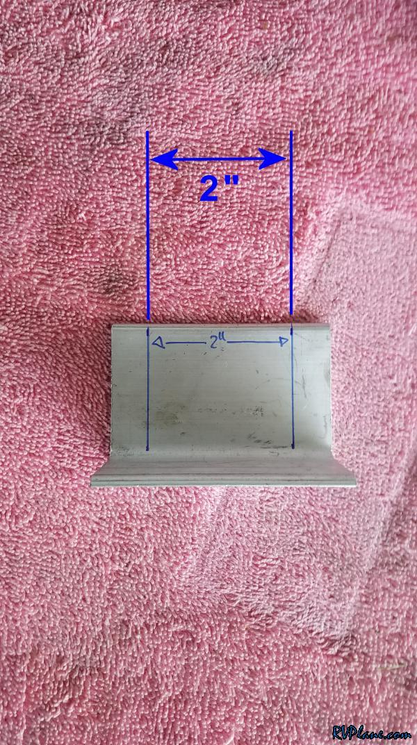 This would leave 1/2" on either side. 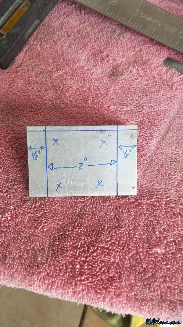 The finished product. 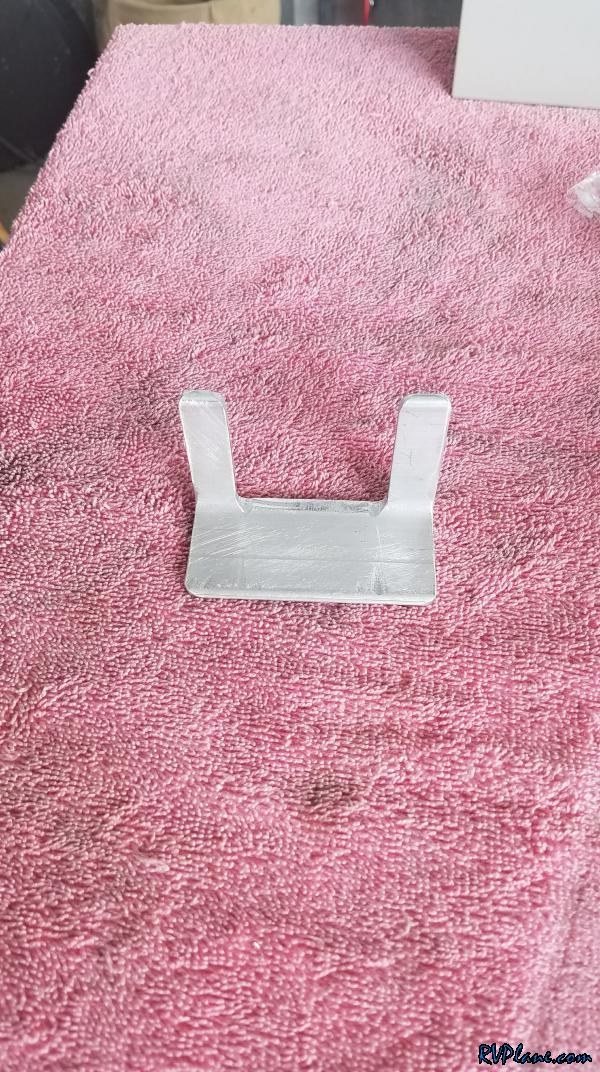 Next I needed (4) 1/4" diameter holes. They would be separated by 2 7/16" horizontally, and 1.5" vertically. Additionally, they would be offset on the vertical axis by 7/16". 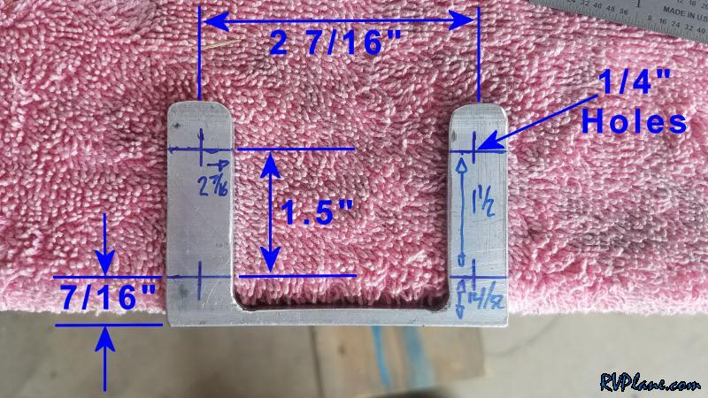 And here's the result - this bracket screws into the existing valve cover holes. 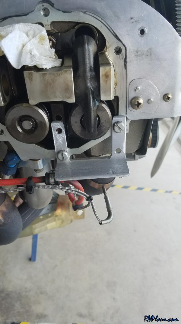 The next step was to "mill" out a hole for the valve compressor to insert into and pivot around. The hold would be offset from the bottom by 1/8", and it would be 7/16" x 1". 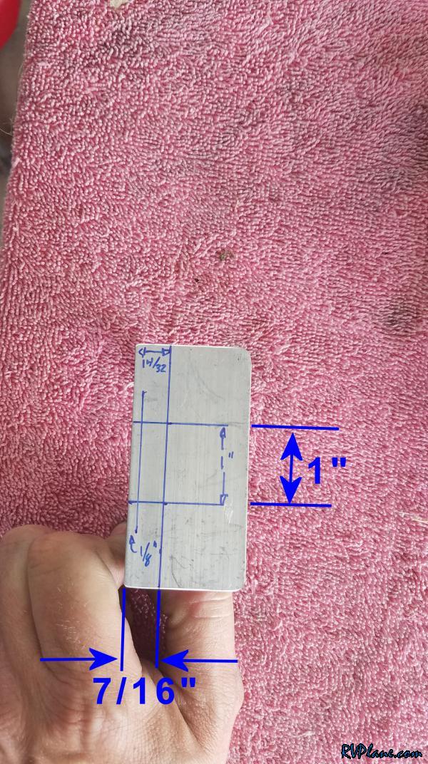 Not my best work, but a 1/8" drill and a unibit with some filing at the end gave me a good enough hole. 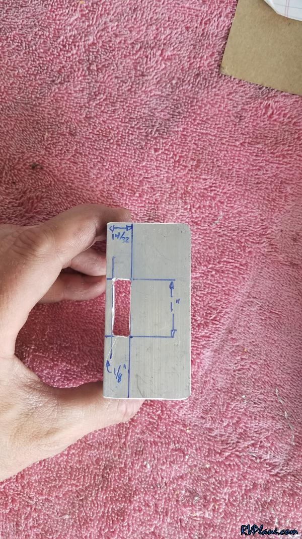 The finished product with my home-made valve compressor next to it. 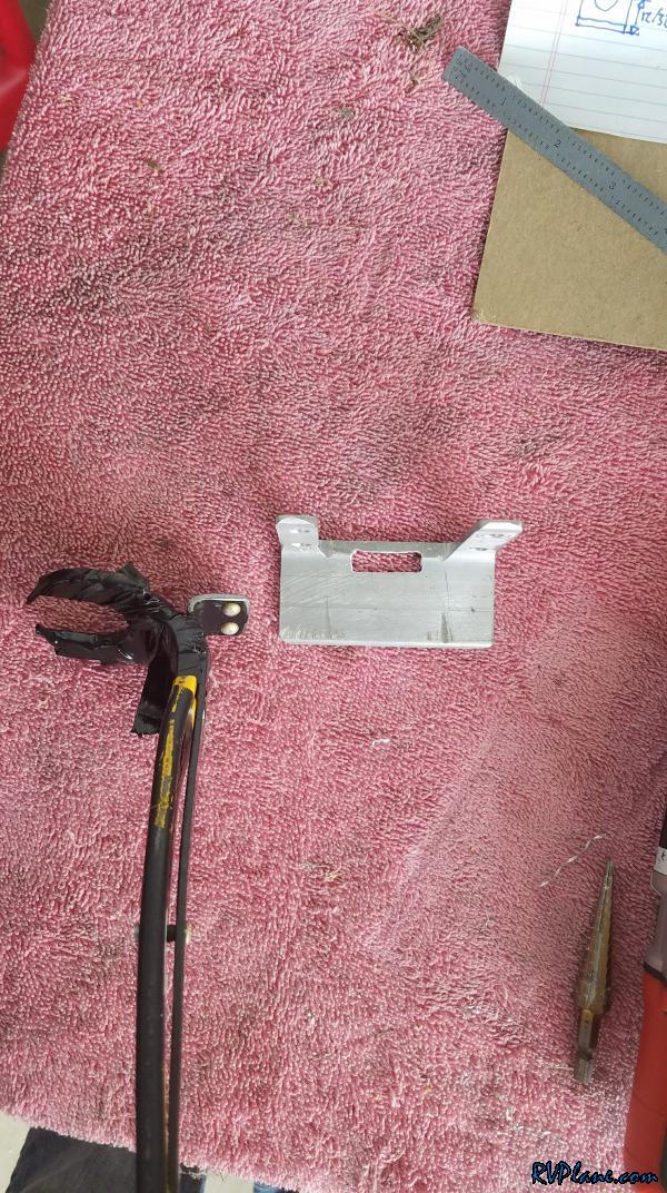 This is how the two parts will interface to each other. The "tab" on the back of the valve compressor tool gets inserted into the "slot" I made in the angle. 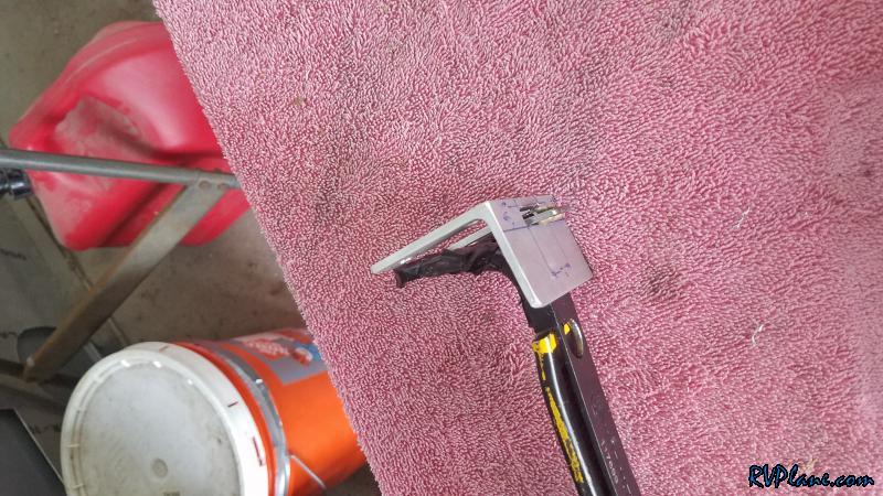 First step is to install the new pivot point angle. 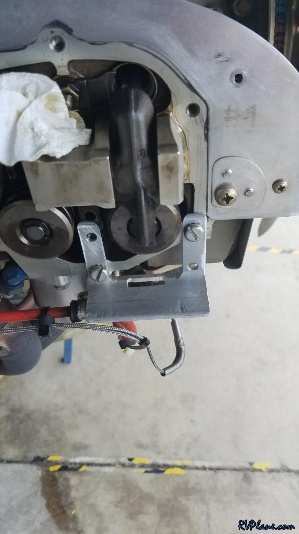 Step two is to insert the tab on the back of the valve compressor tool. Lift the handle up and the spring gets compressed! 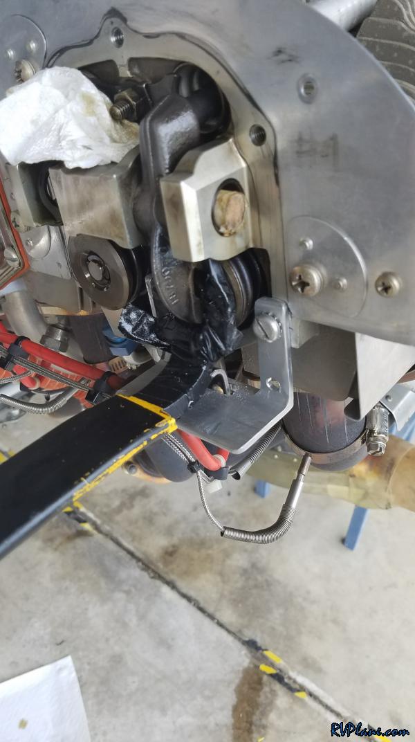 Worked like magic. I was able to install the rocker shaft nearly instantaneously! This additional tool took about an hour to make...and the best part is it was FREE! 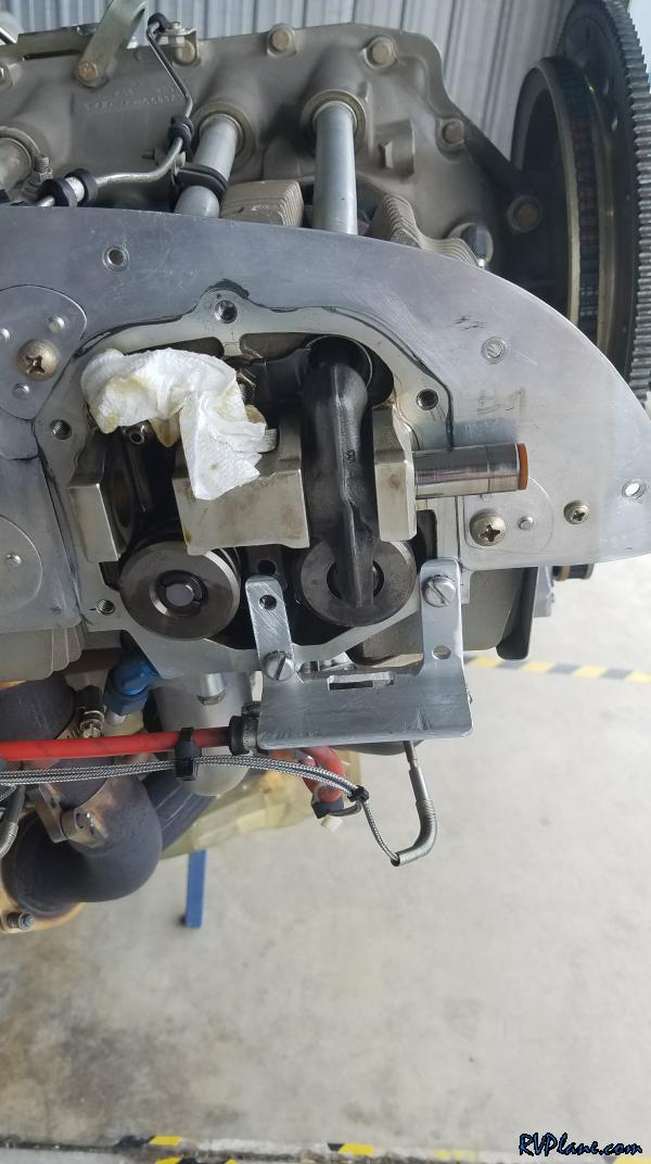
|
|||||
|
http://RVplane.com |
Last Modified: January 31, 2026 |